Robbe Paula III - The Crane Operation
![]() 12 Feb 00 - New page.
12 Feb 00 - New page.
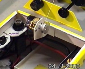
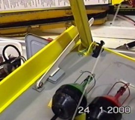
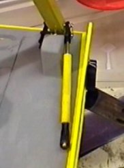
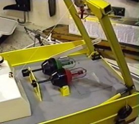
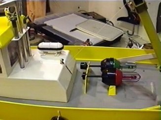
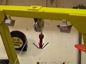
I have been asked a few questions on how the Crane Winch works. To save further questions, I have added the relevant information here. Picture #1 is the winch fitted to the deck, followed by the lock arm (#2) and ram & limit switch box (#3). #4 & #5 are overall views of the rear deck showing arrangement with #5 showing the slot required in the cabin. #6 is a close-up of the gantry head.
 Note: These images are reduced slightly here - click for full size.
The limit switch is merely a lever operated micro switch & can be any with an arm long enough to be formed as shown on the original plans. I had to do quite a lot of reshaping & shorten the arm to get it to work properly, but persevere. The limit switches sole purpose is to stop the winch motor from winding in once the screw hits the switch. In this position the diode cuts the power.
I've also included a diagram showing the wiring for using a dual momentary switch unit as the controller (12.22) - any 2 way or more changeover momentary switch unit will do. I've used an Action universal 2 function switcher or Electronize 4 way switcher which could run other functions as well.
The diagram is drawn with both controller switches off and the micro-switch (12.20) is drawn in the non-pressed position. In this position both motor terminals are positive and the winch is stationary. If the top switch moves the left motor terminal goes negative and the motor pays out, if 12.20 is operated power continues to flow through the circuit. If the bottom switch moves the lead to 12.20 goes negative and the motor pulls in, if 12.20 is operated 12.19 stops the power flow stops. The sprung ram tries to push the gantry backwards which is resisted by the lock arm (when locked or at full travel) and by the brass ball (11.21) on the winch cable when hard up against the gantry stop block (8.12).
The sequence of operations for the winch (from full forward) and launch a buoy is:
1. Start paying out the winch wire.
2. Trigger the lock release servo to lift the lock arm and allow the gantry to move out. The gantry will move out and is controlled by the winch cable until it reaches a stop. On mine once the gantry has passed the lock slot I have to return the servo to the locked position or it binds (& release again at the mid point). When the gantry reaches the slot in the end of the lock arm the winch pays out cable until empty (beware it would then start pulling in again and the switch would not stop it). The buoy floats free.
To retrieve the buoy:
1. Pull the winch cable in until the gantry locks in the mid position.
2. Pay out winch cable to the waterline & manoeuvre into position.
3. Pull in the winch cable (repeat 2 & 3 until captured).
4. Stop the winch where you fancy.
These procedures sound terrible, but it is really easy when you have done it a few times. It is possible to retrieve a buoy from the deck at the start (even from the starboard mount point if you rock the boat). However, it is not possible to return a buoy to the mounts although you can drop it on the deck (& let it roll around).
You may notice in my pictures that the green buoy has an extended base. This houses a battery to power a flashing LED in the light fitting at the top. It is triggered by a mercury tilt switch that is on when vertical and if laying one way up on it's side, but it is off the other way up on it's side. This compliments the other lighting I fitted for potential night sailing's. I will be adding details of this buoy design & a subsequent improvement I'm currently working on.